OPAE AFU Simulation Environment (ASE) User Guide
Intended Audience
This document is written for developers who plan to use AFU Simulation Environment (ASE) as a tool to begin development on the Intel® Xeon®-FPGA Platform with an Intel® FPGA IP (FIM) accelerator before deployment in a real system. The document is intended for both beginners and experienced developers.
To use the ASE Environment, the developer must have access to Accelerated Functional Unit (AFU) source code in RTL format like {System}Verilog, VHDL) or in SystemC, etc. or in a High-level Synthesis (HLS) language, so long as the generated output can be interpreted by industry-common RTL Simulator tools. Application software can be developed to operate this AFU in the same unified environment.
The minimum set of skills required for developing with ASE, is competence in C/C++, synthesizable SystemVerilog development, familiarity with RTL simulators like Synopsys* VCS-MX or Mentor Graphics** ModelSim-SE*/QuestaSim, and preferably some FPGA PAR experience. Additional skills may be necessary and recommended for more advanced work. Teams of developers who specialize in either RTL development or Software development may use ASE in lock-step to develop functional AFUs for Intel® Xeon®-FPGA platform.
Introduction
Intel® Accelerator Functional Unit (AFU) Simulation Environment (ASE) can also be referred as the Intel® Xeon®-FPGA user application development and debug environment. It aims to provide a consistent transaction level hardware interface and software API that allows users to develop production-quality Accelerator Functional Unit (AFU) RTL and software host application that can run on the real FPGA system without modifications.
ASE can be used to develop and simulate AFU and software code that will run on Acceleration Stack for Intel® Xeon® Processor with Integrated FPGA and the Intel® Acceleration Stack for Intel® Xeon® CPU with FPGAs. The figures shown refer to Acceleration Stack for Intel® Xeon® Processor with Integrated FPGA platform, but the enviroment can be used to simulate either of the two platforms.
The ASE environment is integrated to support one AFU and one application at a time. Multiple slot simulation in a single platform is not supported in ASE.
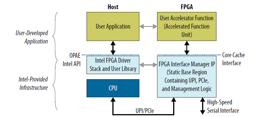
The Acceleration Stack for Intel® Xeon® Processor with Integrated FPGA platform provides coherent accelerator attachment to an Intel platform.
AFU Simulation Environment (ASE) Overview
ASE is a unified environment that aims to reduce time-to-market AFU hardware and software development. It is packaged in Open Programmable Acceleration Engine (OPAE) software distribution.
ASE exposes two interfaces:
- Software: Open Programmable Acceleration Engine (OPAE) API realized in C programming language.
- Hardware: Core Cache Interface (CCI-P) specification realized in SystemVerilog.
You must comply with these interfaces to successfully deploy your IP on the Acceleration Stack for Intel® Xeon® Processor with Integrated FPGA or Acceleration Stack for Intel® Xeon® CPU with FPGAs platform.
Capabilities of ASE
- ASE provides a protocol checker that helps identify protocol correctness. ASE can rule-check if the Accelerator Functional Unit (AFU) complies to CCI-P protocol specifications, and whether OPAE API has been used correctly. It provides methods to identify potential issues early before in-system deployment.
- ASE can help identify certain lock conditions and Configuration/Status Registers (CSR) address mapping and pointer math mistakes.
- ASE presents a fake memory model to the AFU which keeps tabs on memory requested as accelerator workspaces, immediately flagging illegal memory transactions to locations outside of requested memory spaces. This is a good way to identify address violation bugs in simulation.
- ASE does not guarantee synthesizability of the AFU design. However ASE and Intel® Quartus® Prime Pro Edition can be used in an iterative design flow to generate a successfully compiled the Accelerator Function (AF) from AFU RTL functionally verified in ASE for interoperability within the modeled platform.
- ASE provides a data hazard checker which can be used to warn users of CCI-P traffic patterns that may cause Write After Write (WAW), Read After Write (RAW), and Write After Read (WAR) hazards. These transactions may be debugged using the waveform viewer or by using a relevant Memory Protocol Factory (MPF) shim.
- ASE does not require administrator privileges needed to run, it is completely user-level. ASE may be run on a “plain vanilla” user Linux box with all the required tools installed.
Limitations of ASE
When using ASE in the application development cycle, consider the following:
- ASE is a transaction level simulator for a single AFU slot and single application in platform with Intel® FPGA IP. ASE does model either Intel® UPI or PCIe specific packet structures and protocol layers.
- ASE does not simulate caching activities and is not a cache simulator. It cannot reliably simulate cache collision or capacity issues.
- ASE is designed to take an actual in-system AFU RTL and its corresponding OPAE software application and verify them for correctness. ASE cannot simulate a FPGA programming file.
- Although ASE models some latency parameters, it cannot model real-time system-specific latency behavior. It is also not intended to be a timing simulation of the design or latency/bandwidth profile of the real system, but good for functionally correct development.
- ASE does not simulate multi-AFU or multi-socket configurations.
ASE based AFU Design Workflow
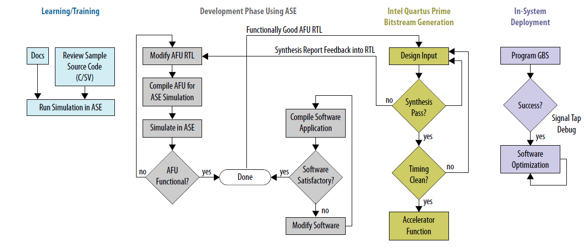
Accelerator Functional Unit (AFU) using ASE can be broken down into four stages.
- Learning/Training: In this step, the user may use ASE to understand the interface specifications and platform overview. Sample code may be reviewed to get an understanding for CCI-P specifications and OPAE Intel API function calls. You may run these samples in ASE simulation.
- Development Phase: In the development phase, ASE is used to develop AFU RTL and Software logic in a single workflow. Design RTL can be either developed from scratch or by modifying existing sample RTL. ASE behaviorally models the FIM IP providing immediate functionality feedback at the development phase. Any errors in CCI-P protocols, transactions, or invalid memory accesses can be flagged off in this stage and fixed at development time, without involving long place and route run times.
- Bitstream Generation: Once functional AFU RTL and software have been developed satisfactorily, the AFU RTL can be seamlessly ported to the Intel® Quartus® Prime Pro Edition and placed-routed for the specific kind of FIM IP (Acceleration Stack for Intel® Xeon® Processor with Integrated FPGA or Acceleration Stack for Intel® Xeon® CPU with FPGAs versions). Synthesis reports can be used as feedback to fix AFU RTL. This can be taken back to Development Phase and functionally validated in ASE. It must be noted that bitstream generation can take hours depending on the design’s complexity, area occupancy, etc. Once a bitstream is generated, timing analysis is performed to check for timing corners, setup-hold violations, clock closure, etc. Feedback or failures from these also can be fed back to the design and validated in the ASE environment. Once all these criteria are sufficed, an AF containing the AFU RTL is generated.
- In-system Deployment: Once a successful AF is generated, this can be tested in system or deployed. Further in-system debug of failures can be performed using the Signal Tap. Platform specific software optimization can be performed in this stage. Platform specific optimizations to the application may be pursued in the same manner as any other software optimization task.
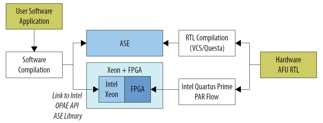
AFU RTL code and OPAE software code produced in ASE is portable between the Simulation and Place-and-Route (PAR) Intel® Quartus® Prime environment. This is valid only if the AFU RTL code developed in the ASE environment is synthesizable and meets timing criteria. * In the simulation environment, the AFU RTL is compiled in either Synopsys* VCS-MX or Mentor Graphics* Modelsim-SE/Questasim tools. The Software application is compiled for an ASE-specific implementation of the OPAE API. * In the in-system environment, the AFU RTL is synthesized in Intel® Quartus® Prime to produce a bitstream. The FPGA is programmed using this bitstream. The Software application is compiled for an platform-specific implementation of the OPAE API.
ASE is capable of consuming AFU code in RTL source form only, and not in Bitstream form.
System Requirements
ASE is available under the Open Programmable Acceleration Engine (OPAE) software release. The current OPAE ASE release support both Acceleration Stack for Intel® Xeon® Processor with Integrated FPGA and Acceleration Stack for Intel® Xeon® CPU with FPGAs platforms. ASE does not require an FPGA in the platform. Bitstream configurations cannot be simulated in ASE.
ASE is supported only on 64-bit Linux operating systems. ASE performs best on a 64-bit RTL simulator, either Synopsys* VCS-MX or Mentor Graphics* QuestaSim/ModelSim-SE, though support for 32-bit ModelSim is available. The RTL simulator-specific requirements are not listed here. Consult with your RTL simulator vendor for Synopsys* or Mentor Graphics* specific requirements.
The following RTL Simulators versions are supported in the current version of ASE:
- Synopsys* VCS-MX (tested versions)
- VCS-MX H2013.06-SP1
- VCS-MX J2014.12-SP3
- VCS-MX K2015.09-SP1
- VCS-MX L2016.06
- Mentor Graphics* Modelsim-SE/Questasim (tested versions)
- QuestaSim 10.5b
- ModelSim-SE 10.5a
- QuestaSim 10.4d
Both Mentor Graphics\* Modelsim-SE/Questasim and Synopsys\* VCS-MX system requirements are different are varied.

ASE is tested in some common configurations including the support list for Mentor\* and Synopsys\*. It is impractical to verify ASE functionality on all possible OS configurations. When choosing an operating system configuration, please consult the RTL Simulator supported OS List.
ASE uses Inter-Process Communication (IPC) constructs. Although under
most circumstances these constructs operate normally without glitches.
The following Linux locations should exist and be writeable. In most
Linux distributions, /dev/shm comes pre-mounted as a default option.
The other ASE requirements are as follows:
- C-Compiler: gcc 4.8.5 or above
- Boost Development libraries
- UUID Development libraries
- JSON Development libraries
- Please see the dependencies of the OPAE System library build process
- Cmake: version 2.8 or above
- GLIBC: version 2.19 or above
- Python: version 2.7 or above
- Intel® Quartus® Prime Pro Edition: If you are simulating the
provided NLB sample, ASE needs to find the
$QUARTUS_HOME/eda/sim_lib/directory supplied with Intel® Quartus® Prime Pro Edition. The NLB sample RTL uses the Intel FPGA gates library.set GLS_SIM to 1 in thease/Makefile.
ASE provides a bash script called env_check.sh in
/sw/opae-x.x.x/ase/scripts directory. Run this script to determine
if you have the required tools installed.
Check the RTL simulator’s product information for supported operating systems, installation notes, and other related information. In general, the RTL simulator must be able to compile SystemVerilog Direct Programming Interface (DPI) constructs, have SystemC support, and be able to compile the standard examples that come with the installation.
Intel does not provide consulting support for installing the RTL simulators from Synopsys* or Mentor Graphics*.
Package Description
ASE may be downloaded either in RPM format (see Download instructions) or as source.
The source directory tree is:
OPAE_BASEDIR
  |-- ase
  | |-- api
  | |   `-- src
  | |-- rtl
  | |   `-- dcp_emif_model
  | |-- scripts
  | `-- sw
  |
  |-- cmake
  |-- common
  | |-- include
  | |   |-- fpga_app
  | |   `-- opae
  | `-- utils
  |-- doc
  |-- libopae
  |-- platforms
  |-- samples
  |-- tests
  `-- tools
The above tree directory roughly depicts the package structure of the ASE distribution. There are a minimum number of directories that are required to successfully build and run the ASE simulator:
ase: ASE simulator implementation location contains several subdirectories, namely:api/src: This directory contains the OPAE Intel ASE implementation. This is compiled into a library that may be statically or dynamically linked.rtl: RTL components of ASE. This must be compiled in the RTL simulator for both programmable FPGA acceleration cards and tightly-coupled FPGA mode simulator builds.dcp_emif_model: programmable FPGA acceleration card Local DDR memory model. This must be compiled for all programmable FPGA acceleration card mode simulation model.
scripts: Contains several helper scripts. These are described in Helper Scripts in ASE Section.sw: Software components of ASE. These are required for all simulations of ASE, and are compiled using GNU Compiler Collection (GCC).
common: This directory contains the OPAE library definitions, and defines various macros for access to an FPGA in an OPAE context.platforms: Contains scripts and RTL for managing the connection between a platform and an AFU’s top-level interface.samples: Contains a sample that will run on Native Loopback (NLB) RTL AFU.libopae: Intel platfrom specific implementation of the OPAE API.
Helper Scripts in ASE
Several scripts are supplied in the ASE distribution under the
ase/scripts directory. These can be used for initialization, help
with setting up tools, and even cleanup of an existing ASE simulation
environment.
Set Up Simulation Tools
To set up the tools required, use ase/scripts/ase_setup_template.sh
as a template script. The script has many empty placeholders that are
site and environment specific. Consult your Electronic Design Automation
(EDA) tools administrator, and/or the RTL simulator User Guides for help
setting up the tools.
ASE Environment Check
This script checks the status of the OS distribution, distro and available system libraries. This is a non-exhaustive check, and looks for only the most important dependencies, e.g. GCC version, GLIBC version, etc.
$ ./scripts/env_check.sh
Simulate an AFU using ASE
An ASE environment for simulating a particular AFU is generated by
replicating the ASE source tree and adding AFU-specific configuration.
Several scripts are provided to accomplish this. The primary script is
afu_sim_setup, which is installed in the OPAE bin directory.
Before attempting to configure ASE, follow the instructions for building
the OPAE SDK and ensure that either the OPAE installed bin or the
OPAE build tree’s bin directory is on your shell’s PATH.
See the ASE Example section below for a sample workload definition and execution flow.
afu_sim_setup
The afu_sim_setup script consumes a file containing a list of RTL
sources and constructs an ASE tree to compile and simulate them. Consult
afu_sim_setup --help for a list of arguments. The only required
argument is the directory in which to construct the new environment. The
--platform argument sets the platform class to simulate (e.g.
integrated Xeon+FPGA with a coherent FPGA-side cache or a discrete
PCIe-attached FPGA). afu_sim_setup is a wrapper for other scripts,
described below. It invokes rtl_src_config to transform the list of
RTL sources into simulator configuration files.
generate_ase_environment.py is invoked to instantiate a simulated
platform configuration. Users could choose to invoke these scripts
directly, though interacting only with afu_sim_setup should satisfy
most requirements.
$ afu_sim_setup --sources=<rtl_sources.txt> <target dir>
rtl_src_config
The rtl_src_config script maps a simple text file containing a list
of RTL source files into either an ASE configuration file for simulation
or a Quartus configuration file for synthesis. In addition to sources,
preprocessor variables may be defined. Source configuration files may be
hierarchical, with one file including another. Scripts are provided for
constructing either ASE-based simulation trees or Quartus build trees,
driven by rtl_src_config. Run rtl_src_config --help for a list
of options and for documentation of the expected source specification
syntax.
generate_ase_environment.py
The generate_ase_environment.py script is invoked by
afu_sim_setup to generate a number of platform configuration files.
We recommend that most users use a list of RTL sources through
afu_sim_setup and allow that script to invoke
generate_ase_environment.py in the background. A legacy mode in
generate_ase_environment.py does a brute-force check of supplied AFU
RTL directories, attempting to define a compilation. The script is
imperfect and lists every file ending in .sv, .vs, .vhd, or .v and
directories separated by +. It also may fail when compilation is
order-dependent.
Invoke generate_ase_environment.py --help for a list of options.
- Mandatory Option: The script requires a directory path to RTL AFU.
- Optional -t: By default the tool option selected is
VCS. If Mentor* tools are used, supply theQUESTAoption. - Optional -p: By default Acceleration Stack for Intel Xeon
Processor with Integrated FPGA
intg_xeonoption is selected. If Acceleration Stack for Intel Xeon CPU with FPGAs is used, supply thediscreteoption. - Optional -x: Exclsions for path searches can be supplied using this option.
Along with the AFU configuration files, depending on the RTL tools used,
certain tool control scripts are generated. * VCS: In VCS
configuration, synopsys_sim.setup and vcs_run.tcl files are
created. * QUESTA: In QUESTA configuration, vsim_run.tcl
file is created.
The .tcl files are used at simulation run-time.
Details on generated files: * vlog_files.list lists all the Verilog
and SystemVerilog files found in the AFU directory path *
vhdl_files.list lists all the VHDL files found in the AFU directory
path. * ase_sources.mk ties the above two files into
DUT_VLOG_SRC_LIST and DUT_VHD_SRC_LIST Makefile variables. *
ASE_PLATFORM is set to the platform type selected or to the default
type. * Extra VCS or QUESTA options may be set using the
SNPS_{VLOGAN,VHDLAN,VCS}_OPT or MENT_{VLOG,VCOM,VSIM}_OPT
options in the Makefile. See ASE Makefile
Variables for more information.
Absolute paths are used wherever possible. One helpful option to use for portability across users and groups may be to use an environment variables may be used. These can be used directly in the generated files for building and running the simulator.
You must manually check this file for correctness before using it in the simulation.
Clean ASE Environment
The ASE cleanup script located at scripts/ipc_clean.py may be used
for killing zombie simulation processes and temporary files left behind
by failed simulation processes or crashes.
$ ./scripts/ipc_clean.py

############################################################
#                                                          #
#                ASE IPC Cleanup script                    #
#                                                          #
############################################################
IPC mounts seem to be readable... will attempt cleaning up IPC constructs by user ' user_foo '
Removing .ase_ready file ...
Type 'y' to clean up all zombie ase_simv processes : y
Going ahead with cleaning up ASE processes opened by  user_foo
$
ASE Usage
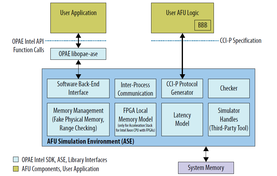
AFU Simulation Environment (ASE) is structured as a server-client simulation environment. Broadly speaking the AFU RTL is compiled into a simulator server process and the application compiled/linked against OPAE ASE library forms the client process. Communications between server and client is done using named pipes. Most of the simulation infrastructure is abstracted in ASE code, and does not require any user modifications.
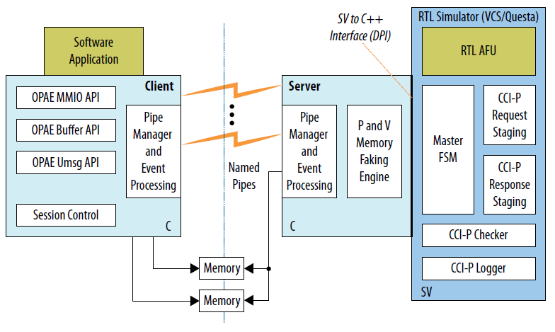
- Server Process:
- Server process interfaces with 3rd Party RTL Simulator packages (currently Mentor* Modelsim-SE, Questasim and Synopsys* VCS-MX are supported) via SystemVerilog-DPI library and interface to the simulator software.
- Communication to client is achieved using Named Pipes. A pipe event monitoring engine is also built into the server process. Communication about control, status and session management is done using the named pipes.
- The server process also exposes a “fake” physical memory modeling engine that allows the RTL AFU to access “physical” addresses. Virtual to “fake physical” address translations are handled in this block.
- CCI-P interface is managed in SystemVerilog. All CCI-P events are logged and time stamped.
- The server also includes a CCI-P Checker block that rule-checks CCI-P transactions originating in the AFU. This allows for development-time live checking of protocol issues, and early warning of CCI-P protocol non-compliance, hazards, race conditions, etc.
- Lastly, the buffer allocation calls are mapped to POSIX Shared
Memory (
/dev/shm). Information about these buffers are shared back and forth between server-client processes using the named pipes.
The Physical addresses generated in ASE are not realistic and are not replicable in-system.
- Client Process:
- Client primarily implements an OPAE interface and a library to ASE’s implementation of platform capabilties like MMIO, Buffer management, session control. Actual features are available based on what platform is configured in the build stage. These are exposed using OPAE API’s functions.
- A compiled program would compile/link against the ASE implementation of OPAE library. All OPAE calls will routed to ASE instead of the OPAE platform driver.
The two processes (both server and client) are built using two separate build scripts.
- Client: OPAE library implementations for System and ASE are built
using the main
cmakescript supplied at the base of the distribution. The libary produced will be installed inlibdirectory (depending on the install method). - Server: ASE Server process (containing the ASE Software,
Systemverilog engines and the AFU RTL logic code) are compiled using
a Makefile located inside the
asedirectory.
AFU Build Instructions
ASE Application (Client) Build Instructions
If you downloaded a source tarball, you will need this step, else go directly to the Application build step.
For these instructions, the directory ``/tmp/opae/`` is used as the base directory where OPAE API software distribution is installed. ``/tmp`` prefix may point to any system or user directory.

ASE Source directory will point to ``/tmp/opae/ase/``
- To build the OPAE libraries:
# Change directory to opae directory
$ cd /tmp/opae/

# Check contents
$ ls
ase  cmake  CMakeLists.txt  common  doc  libopae  mybuild  README  samples  tests  tools

# Create an out-of-build directory, and change to it
$ mkdir mybuild
$ cd mybuild

# Configure the software build using cmake (see options)
# $ cmake <Path to CMakeLists.txt>
# Install directory, in this example is <Path  to opae>/myinst/

$ cmake ../ -DBUILD_ASE=YES -DCMAKE_INSTALL_PREFIX=/tmp/opae/myinst/
-- The C compiler identification is GNU 4.8.4
-- The CXX compiler identification is GNU 4.8.4
-- Check for working C compiler: /usr/bin/cc
-- Check for working C compiler: /usr/bin/cc -- works
.
.
.
-- Configuring done
-- Generating done
-- Build files have been written to: /tmp/opae/mybuild

# Build and install libraries
$ make
$ make install

# The environment Variable PATH should be pointed to /myinst/bin
# Check library install paths
$ cd /tmp/opae/myinst/
$ ls
doc  include  lib

$ ls lib
libopae-c-ase.so  libopae-c.so  libopae-c.so.0  libopae-c.so.0.1.0 ...
The software application must be built for ASE using
libopae-c-ase.so using a gcc command. The three methods of
building the software application are described below:
Dynamically linking libopae-c-ase.so
# Change directory to <Path to Directory>/opae/samples/
#   -luuid is required by UUID code
#   -lopae-c-ase is required for linking against ASE library
#
$ gcc -g -o hello_fpga hello_fpga.c -L /tmp/opae/myinst/lib/ -I /tmp/opae/myinst/include/ -luuid -lpthread -lopae-c-ase -std=c99

# When running the application, use
# Make sure the relevant LD_LIBRARY_PATH variable is set
$ ./hello_fpga
The ASE implementation of the OPAE library attempts to functionally
mirror system behavior. Hence, the application may also be dynamically
linked to the System library, and then overloaded with the
LD_PRELOAD environment.
# Change directory to <Path to Directory>/opae/samples/
#   -luuid is required by UUID code
#   -lopae-c is required for linking against ASE library
#
$ gcc -g -o hello_fpga hello_fpga.c -L /tmp/opae/myinst/lib/ -I /tmp/opae/myinst/include/ -luuid -lpthread -lopae-c -std=c99

# When running the application, use
# Make sure the relevant LD_LIBRARY_PATH variable is set
# ASE_WORKDIR environment variable must also be set.
$ LD_PRELOAD=libopae-c-ase.so ./hello_fpga
Compiling the libopae-c-ase.so library with OPAE Software Application
A much simpler method to use the OPAE ASE library implementation and compile it to the OPAE software application directly in one command using GCC.
# Compile command
$ gcc -g -o hello_fpga_ase hello_fpga.c /tmp/opae/myinst/lib/libopae-c-ase.so -I /tmp/opae/myinst/include/ -std=c99 -luuid

# When running the application, start the simulator
# Then set LD_LIBRARY_PATH and ASE_WORKDIR
$ ./hello_fpga_ase
ASE Simulator (Server) Build Instructions
ASE uses a platform differentiation key in the simulator Makefile to enable different platform features and produces a simulator configuration based on that.
You must note the following REQUIRED Build configurations
| Configuration | Description | Default |
|---|---|---|
ASE_PLATFORM |
This is the
platform
differentiator
must be set in
ase_sources.
mk
to point to
the required
simulator
features.
FPGA_PLATF
ORM_INTG_XEON`
`
and
``FPGA_PLATFOR
M_DISCRETE
are the only
legal values. |
FPGA_PLA
TFORM_INTG
_XEON |
SIMULATOR |
This must be
set in
ase_sources.
mk
to point to
the correct
kind of RTL
simulator.
Currently
Synopsys*
VCS-MX and
Modelsim-SE
(Questasim)
simulator
builds are
supported in
ASE. Only
64-bit
configurations
are supported.
VCS and
QUESTA are
the only legal
values. |
VCS |
DUT_VLOG_SRC_L
IST
,
DUT_VHDL_SRC_L
IST
,
and
DUT_INCDIR |
These options point to AFU Verilog, VHDL and include path settings required for RTL simulators to build the simulation model correctly | None supplied — You must fill this. |
For more information on other switches see ASE Makefile targets
To generate the AFU specific files for the simulator build, you may use
the scripts/generate_ase_environment.py script. This script is
imperfect, and will require manual inspection of generated
configurations in order to get correct operation.
Any AFU RTL specific define macros or include paths must be edited in ``ase_sources.mk``.
You may use the Generate ASE
Environment script to generate the
required AFU ase_sources.mk and vlog_files.list.
# change to ASE directory
$ cd /tmp/opae/ase/

# Use the scripts/generate_ase_environment.py
$ ./scripts/generate_ase_environment.py -t VCS -p discrete <Path to sample RTL>
.
.
.
# Edit files as needed.

$ ls
ase_sources.mk  vcs_run.tcl  synopsys_sim.setup  vlog_files.list  ...
The vlog_files.list and ase_sources.mk files may need to be
checked manually for correctness. The simulator is now be built with a
‘make’ command.
$ cd <opae>/ase/
$ make
.
.

$ ls work/ase_simv
work/ase_simv
ASE Runtime Instructions
Broadly in the server-client configuration of ASE, the server (ASE simulator) is invoked first, then the client software application is invoked next along. The run time options are shown here.
$ make sim \
  [SIMULATOR=<VCS|QUESTA>] \
  [ASE_CONFIG=<Path to ase.cfg>] \
  [ASE_SCRIPT=<Path to ase_regress.sh if ASE_MODE=4>]
For a start, Intel recommends using two terminal windows.
Terminal 1: When make sim is run, When the simulator is invoked,
ASE initializes and the AFU, issues a reset and then waits for
transactions to come in. The software application must wait until “Ready
for Simulation” message is displayed in Terminal 1.
The environment variable ASE_WORKDIR is indicated in Terminal 1.
# Invoke the simulator
$ make sim
SIMULATOR=VCS
CC=gcc
#################################################################
#                                                               #
#             OPAE Intel(R) Xeon(R) + FPGA Library              #
#               AFU Simulation Environment (ASE)                #
#                                                               #
#################################################################
ASE platform set to MCP_SKYLAKE mode
.
.
.
SIM-SV: Transaction Logger started
SIM-SV: Simulator started...
SIM-C : +CONFIG /tmp/opae/ase/ase.cfg file found !
SIM-C : +SCRIPT /tmp/opae/ase/ase_regress.sh file found !
SIM-C : PID of simulator is 41819
SIM-C : Reading /tmp/opae/ase/ase.cfg configuration file
SIM-C : ASE was started in Mode 1 (Server-Client without SIMKILL)
        ASE mode                   ... Server-Client mode without SIMKILL
    Inactivity kill-switch     ... DISABLED
    Reuse simulation seed      ... ENABLED
    ASE Seed                   ... 1234
    ASE Transaction view       ... ENABLED
    User Clock Frequency       ... 312.500000 MHz, T_uclk = 3200 ps
    Amount of physical memory  ... 128 GB

.
.
.
SIM-C : ** ATTENTION : BEFORE running the software application **
  Set env(ASE_WORKDIR) in terminal where application will run (copy-and-paste) =>
  $SHELL   | Run:
  ---------+---------------------------------------------------
  bash/zsh | export ASE_WORKDIR=/tmp/opae/ase/work
  tcsh/csh | setenv ASE_WORKDIR /tmp/opae/ase/work
  For any other $SHELL, consult your Linux administrator

  SIM-C : Ready for simulation...
  SIM-C : Press CTRL-C to close simulator...
Terminal 1 make sim can be closed by issuing a SIGTERM to
the relevant ase_simv process or by sending the CTRL-C
keystroke.
Terminal 2: First set an environment variable ASE_WORKDIR as
seen in Terminal 1. In this example ASE_WORKDIR is set to
/tmp/opae/ase/work. Then invoke the software application.
# Set ASE_WORKDIR environment variable
$ export ASE_WORKDIR=/tmp/opae/ase/work/

# Run the application
$ export LD_LIBRARY_PATH=/tmp/opae/myinst/lib/
$ LD_PRELOAD=libopae-c-ase.so ./hello_fpga
When simulation is completed (application has exited), the simulator must be closed so the waveform dump process may get completed. On **Terminal 1**, issue a ``CTRL-C`` command.
<Simulator running>
.
.
.
SIM-C : Ready to run next test
818602500C0Tx AlmFull toggled from 1 to 0

818602500C1Tx AlmFull toggled from 1 to 0

<CTRL-C Key hit>

^CSIM-C : Closing message queue and unlinking...
SIM-C : Unlinking Shared memory regions....
SIM-C : Session code file removed
SIM-C : Removing message queues and buffer handles ...
SIM-C : Cleaning session files...
SIM-C : Simulation generated log files
  Transactions file       | $ASE_WORKDIR/ccip_transactions.tsv
  Workspaces info         | $ASE_WORKDIR/workspace_info.log
  ASE seed                | $ASE_WORKDIR/ase_seed.txt

SIM-C : Tests run     => 1
SIM-C : Sending kill command...
SIM-SV: Simulation kill command received...

Transaction count |       VA      VL0      VH0      VH1 |    MCL-1    MCL-2    MCL-4
========================================================================================
MMIOWrReq           9 |
MMIORdReq           2 |
MMIORdRsp           2 |
UMsgHint            0 |
UMsgData            0 |
RdReq           16384 |        0        0    16384        0 |    16384        0        0
RdResp          16384 |        0        0    16384        0 |
WrReq           16385 |        0        0    16385        0 |    16385        0        0
WrResp          16385 |        0        0    16385        0 |    16385        0        0
WrFence             1 |        0        0        1        0 |
WrFenRsp            1 |        0        0        1        0 |

$finish called from file "/tmp/opae/ase/rtl/ccip_emulator.sv", line 2657.
$finish at simulation time           1514962500
V C S   S i m u l a t i o n   R e p o r t
Time: 1514962500 ps
CPU Time:    142.500 seconds;       Data structure size:   1.1Mb
Tue Jun 20 13:29:13 2017
At the end of the simulation, the following files are generated:
- Waveform dump: Depending on whether
VCSorQUESTAis used, a different waveform file is generated.make wavewill open the waveform for the selected tool.inter.vpd: VCS Waveform filevsim.wlf: Mentor/Questa waveform file.
$ASE_WORKDIR/ccip_transactions.tsv: CCI-P Events log listing all events observed in CCI-P interface. The timestamps indicate the corresponding time interval in the waveform dump VPD file.$ASE_WORKDIR/workspace_info.log: Information about buffers opened by the simulation.$ASE_WORKDIR/ase_seed.txt: Information about simulation seed.$ASE_WORKDIR/ccip_warnings_and_errors.txt: Information about CCI-P warnings and errors.
Recommendations List
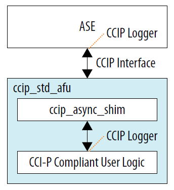
ccip_logger.svis a module in ASE (located atase/hw/ccip_logger.sv) and can be used to log CCI-P events if there are interfaces inside the AFU which conform to CCI-P protocol. This is common for designs that use the Intel® FPGA IP Basic Building Blocks (BBB). This can be used to compare transactions and traffic flow through various CCI-P interfaces.
When instantiating ``ccip_logger`` in multiple locations, distinct file names must be used in each module instantiation.
- ASE uses a simulation shutdown mechanism that gracefully closes all
mutexes, locks, POSIX structures safely before exiting via
$finishstatement in SystemVerilog. If your AFU design uses as$erroror$finishto identify error conditions while simulating, consider using the handlestart_simkill_countdown()instead.start_simkill_countdown()calls$finishafter completing the steps for a graceful shutdown. - ASE simulations can be easily scripted. When the simulator becomes
ready for use, a lock file is written in the work directory. The lock
file name is
$ASE_WORKDIR/.ase_ready.
# Start Simulator in background
make sim &

# Wait for simulator readiness
# When .ase_ready is created in the $ASE_WORKDIR, ASE is ready for simulation
while [ ! -f $ASE_WORKDIR/.ase_ready.pid ]
do
  sleep 1
done

# Start application
cd $PATH_TO_APPLICATION

# Export ASE_WORKDIR variable
export ASE_WORKDIR={Path to simulator mentioned in ASE green printout}
./Application
- If the ASE simulation is too slow, try one of these methods to speed
up the simulation:
- Switch OFF wave dumps: Check your RTL vendor’s recommendation on switching off wave form dumps. In some cases, it may be possible to generate wave dumps for only specific module hierarchies.
- In
ase.cfg, setENABLE_CL_VIEW = 0. This will prevent events from being printed on the screen.
- The latency model of ASE can be modified to generate random patterns
of CCI-P transactions for every run. The latency model settings are
located at
$ASE_SRCDIR/rtl/platform.vh. The*_LATRANGEconstraints are set up as a pair and coded as follows:
`define X_LATRANGE min, max
The min and max values refer to the minimum and maximum cycle
counts after which responses will be returned back to the AFU. During
simulation, a transaction is assigned a latency value randomly picked
from this (min, max) range. The larger the difference between (min,
max), the bigger the standard deviation of latency for a given type of
transaction. Transaction latencies for RDLINE, WRLINE and other
transactions can be individually selected.
None of these values can be implied to be the actual latencies of different transactions when running on the FPGA platform. These settings must be used for simulation and testing only.
/*
 * Latency model
 * Coded as a Min,Max tuple
 * -------------------------------------------------------
 * RDLINE_LATRANGE : ReadLine turnaround time
 * WRLINE_LATRANGE : WriteLine turnaround time
 * UMSG_LATRANGE   : UMsg latency
 * INTR_LATRANGE   : Interrupt turnaround time
 *
 * LAT_UNDEFINED   : Undefined latency
 *
 */
`define MMIO_LATENCY                15
`define RDLINE_S_LATRANGE          20,118
`define RDLINE_I_LATRANGE          20,118
`define WRLINE_M_LATRANGE          20,118
`define WRLINE_I_LATRANGE          20,118
`define UMSG_START2HINT_LATRANGE   39,41
`define UMSG_HINT2DATA_LATRANGE    41,45
`define UMSG_START2DATA_LATRANGE   82,85
`define INTR_LATRANGE              10,15

`define LAT_UNDEFINED              300

`define RDWR_VL_LATRANGE           20,118
`define RDWR_VH_LATRANGE           240,270

`define ASE_MAX_LATENCY            300
- ASE includes a CCI-P protocol checker module (located at
$ASE_SRCDIR/rtl/ccip_checker.sv). Intel recommends to use this for analyzing CCI-P compliance when simulating designs in ASE. The checker sniffs transactions, conditions and header settings and flags them off as either warnings or errors. Multiple classes of issues can be identified using the hw/ccip_sniffer.sv. All checker warnings and errors are logged into$ASE_WORKDIR/ccip_warnings_and_errors.txt.
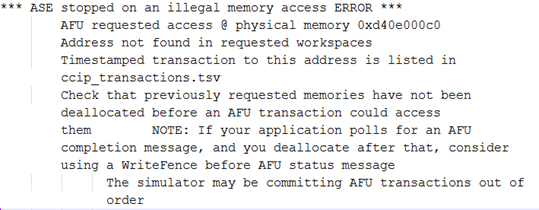
* Memory errors in transactions: This is flagged off with the highest severity. Simulation stops immediately and the transaction is immediately flagged off. The memory error is logged at ```$ASE_WORKDIR/ase_memory_error.log```. The erroneous transaction can be traced back using ```$ASE_WORKDIR/ccip_transactions.tsv```. The timestamp value can be found in the transaction log itself.

* Protocol errors marked as “[ERROR]” in ```$ASE_WORKDIR/ccip_warning_and_errors.txt```: These are protocol errors found by ASE are flagged off immediately and the simulation stops on finding the event. The timestamps are noted and can be co-related with timestamps from the transaction log.

* Protocol warnings marked as “[WARN]” in ```$ASE_WORKDIR/ccip_warning_and_errors.txt```: These are protocol warnings found by ASE and do not cause a simulation stoppage. There are many minor events that may cause this (e.g. X/Z found in the transaction, reset ignorance).
Memory hazards (RAW, WAR and WAW hazards) may also be flagged off by ASE.
ASE Example
A tutorial for CCI-P systems is available in a separate Basic Building
Blocks repository in the
samples/tutorial
tree. The first example,
01_hello_world
follows the afu_sim_setup flow described above. Start with the
tutorial’s
README
file for configuration and execution instructions. The example defines a
set of sources and walks users through the process of creating an ASE
tree, running the simulator and connecting it to a host program.
Operation Reference
ASE Simulator Makefile Switches
The ASE Makefile template consists of many targets and switches. These are described in this section. While this template is only an example and may work for you, for complicated simulation scenarios, users are advised to build their own compilation script.
Synopsys* VCS-MX 64-bit and Mentor Graphics* Modelsim-SE/Questasim 64-bit are the only simulation products supported in ASE. For a complete listing including the versions supported, see System Requirements section.
ASE Makefile Build Flow
The steps to compile ASE Simulator are as follows:
- Step 1: Compile Software objects of ASE into a library file
- The Software components located in
ase/sw/directory is first compiled into software library.
- The Software components located in
``SIM_SIDE`` must be defined as a compilation macro when compiling the ASE simulator objects. This is not the same as the OPAE ASE software library.
- Step 2: Compile ASE Systemverilog files located in
ase/rtl/directories- ASE RTL components based on Acceleration Stack for Intel Xeon CPU with FPGAs or Acceleration Stack for Intel Xeon Processor with Integrated FPGA modes are compiled into the chosen simulation databases.
- If Acceleration Stack for Intel Xeon CPU with FPGAs mode is selected, the EMIF Memory controller model is compiled into the ASE environment.
- If Intel FPGA Gate libraries are required, these models will have to be compiled into the ASE environment.
- Step 3: Compile AFU components into the ASE environment.
- Use the RTL simulator software tools to compile the AFU components. VHDL or {System}Verilog components may be compiled using the Synopsys* or Mentor utilities.
ASE Makefile Targets
| Target | Description |
|---|---|
all |
Default build target, attempts a simulator build in Synopsys* VCS-MX |
header |
Print version and preamble |
check |
Environment check |
sw_build |
Build
ase/sw/
components
into software
library.
SIM_SIDE
switch is used
to build the
simulator
software
components |
help |
Print help information |
vcs_build |
Synopsys* VCS-MX template build flow |
questa_build |
Mentor Graphics* Modelsim-SE/Qu estasim template build flow |
sim |
Start the ASE Simulator |
wave |
Open Selected RTL Waveform Viewer |
clean |
Clean build, simulation, and log files |
distclean |
Clean distribution - removes the AFU configuration files as well |
ASE Makefile Variables
| Makefile target | Description | Default value |
|---|---|---|
VCS_HOME |
Synopsys* VCS-MX installation path | Tool Installation Specific |
MTI_HOME |
Mentor installation path | Tool Installation Specific |
QUARTUS_HOME |
Intel® Quartus® Pro installation path | Tool Installation Specific |
ASE_PLATFORM |
Platform
selection
switch: Either
tightly-couple
d
FPGA or
programmable
FPGA
acceleration
card may be
selected using
FPGA_PLATFOR
M_INTG_XEON
and
FPGA_PLATFOR
M_DISCRETE
respectively |
FPGA_PLATFORM_
INTG_XEON |
SIMULATOR |
Simulator Key
to environment
Allowed values
VCS or
QUESTA |
VCS |
ASE_SRCDIR |
ASE Source location | Current source path |
ASE_WORKDIR |
Location where
ASE runs
(usually
$ASE_SRCDIR/
work
) |
Environment specific execution path |
WORK |
Simulation library compilation location | work |
| ``ASE_DISABLE_LOGGER` ` | Switch to disable logger build | 0 |
| ``ASE_DISABLE_CHECKER `` | Switch to disable checker build WARNING: This can have side effects on protocol correctness | 0 |
GLS_SIM |
Enable gate simulation build | 1 |
GLS_VERILOG_OPT |
Libraries that enable Altera gate simulation | Quartus EDA Simulation library paths |
ASE_CONFIG |
ASE Run-time configuration file (described `here <#ase-ru ntime-configur ation-options> `__) | $ASE_SRCDIR/as
e.cfg |
ASE_SCRIPT |
ASE Regression script path | $ASE_SRCDIR/as
e_regress.sh |
TIMESCALE |
Simulator timescale | 1ps/1ps |
ASEHW_FILE_LIST |
ASE RTL File list | see
ase/Makefile |
ASE_MEM_FILE_LIST |
ASE RTL file list for programmable FPGA acceleration card mode memory | see
ase/Makefile |
ASE_INCDIR |
ASE Include directory paths | see
ase/Makefile |
ASE_TOP |
ASE top level entity (must not be changed) | ase_top |
CC_OPT |
ASE Software Library compiler build options | ``-g -m64 -fPIC -D SIM_SIDE=1 -I
w/ -D SIMULATOR= VCS -D $(ASE_PLA TFORM) -Wall -I $(VCS_HOME)/incl ude/`` |
ASE_LD_SWITCHES |
ASE Software Linker switches |
|
SNPS_VHDLAN_OPT |
Synopsys*
VCS-MX VHDL
compile
options (extra
options may be
added into
ase_sources.
mk
) |
see
ase/Makefile |
SNPS_VLOGAN_OPT |
Synopsys*
VCS-MX
{System}Verilo
g
compile
options (extra
options may be
added into
ase_sources.
mk
) |
see
ase/Makefile |
SNPS_VCS_OPT |
Synopsys*
VCS-MX options
for building
simulator
executable
(extra options
may be added
into
ase_sources.
mk
) |
see
ase/Makefile |
SNPS_SIM_OPT |
Synopsys*
VCS-MX
Simulation
options (extra
options may be
added into
ase_sources.
mk
) |
see
ase/Makefile |
MENT_VCOM_OPT |
Mentor*
Modelsim-SE/Qu
estasim
VHDL compile
options (extra
options may be
added into
ase_sources.
mk
) |
see
ase/Makefile |
MENT_VLOG_OPT |
Mentor*
Modelsim-SE/Qu
estasim
{System}Verilo
g
compile
options (extra
options may be
added into
ase_sources.
mk
) |
see
ase/Makefile |
MENT_VSIM_OPT |
Mentor*
Modelsim-SE/Qu
estasim
VHDL
simulation
options (extra
options may be
added into
ase_sources.
mk
) |
see
ase/Makefile |
DUT_VLOG_SRC_LIST |
Points to a
text file
listing AFU
{System}Verilo
g
files (usually
vlog_files.l
ist
) |
User Generated |
DUT_VHDL_SRC_LIST |
Points to a
text file
listing AFU
VHDL files
(usually
vhdl_files.l
ist |
User Generated |
DUT_INCDIR |
Lists AFU
include
directories
separated by a
‘+’ (usually
in
ase_sources.
mk
) |
User Generated |
ASE Runtime Configuration Options
The ASE configuration file is a text file that can be used to configure
simulator behavior. An example configuration script is available at
ase/ase.cfg
| Switch Name | Default | Description |
|---|---|---|
ASE_MODE |
1 | Modes in
which ASE
can be run1
: Standard
Server-Clien
t
Mode2 :
Simulator is
closed after
ASE_TIMEOU
T
clocks3 :
Software
shuts down
simulator
when client
application
releases
session 4 :
Regression
mode invoked
by script>=5
: Ignored
(revert to
``ASE_MODE=1
``) |
ASE_TIMEOUT |
50000 (only if ASE_MODE=2) |
Watchdog
timer shuts
down
simulator
after
ASE_TIMEOU
T
clocks of
CCI-P
interface
inactivity. |
ASE_NUM_TESTS |
500 (only if ASE_MODE=4) |
Number of tests in regression mode. Failure to set this number correctly, may cause the simulator to exit pre-maturely or to keep waiting for tests to get started. |
ENABLE_REUSE_SEED |
1 | Reuses simulation seed, for the same application, CCI-P transactions are “re-playable ”, i.e., the addresses used can be re-played.Wh en set to 0, obtains a new seed. |
ASE_SEED |
1234 (only if
ENABLE_REUSE_SEED=1) |
ASE seed
setting,
this is used
only when
ENABLE_REU
SE_SEED
is set to 1,
else a
different
seed is
used. At the
end of the
simulation,
a
$ASE_WORKD
IR/ase_seed.
txt
file is
written with
the
currently
used seed. |
ENABLE_CL_VIEW |
1 | ASE verbosely prints all CCI-P transactions . On long simulation runs, setting this to 0 may speed up simulation. |
PHYS_MEMORY_AVAILABLE_
GB |
32 | Restricts ASE address generation to within this memory range. |
Logging Verbosity Control
ASE supports verbosity control of logging messages. In general, three
logging levels are supported: * ASE_INFO: Mandatory information
messages required to indicate operation * ASE_ERR: Error messages
during operation * ASE_MSG: General messages indicating
check-points in ASE. These can be silenced by setting the environment
variable ASE_LOG to 0. By default, these messages are printed on
stdout
ASE_LOG=0 can be used while running the application, something like
this:
$ ASE_LOG=0 LD_PRELOAD=libopae-c-ase ./hello_fpga
In the simulator, two types of messgaes are generated: * CCI-P
events generated by the AFU: These can result in a large amount of
print-out depending on the type of simulation. these can be controlled
using ENABLE_CL_VIEW=0 in ase.cfg file. * ASE_LOG=0
environment variable setting will find minimal use since there is only
minimal ASE events that may generate these. Warnings and errors may not
be suppressed.
Troubleshooting and Error Reference
The following are a non-conclusive list of errors and warnings that one may see in ASE.
| Observation | Problem | Next Steps |
|---|---|---|
| Either all transactions are not seen or simulation ends earlier than expected. | ASE Simulation inactivity is too short for the application use-case to be successfully simulated in ASE. | If using ASE_MODE=2
(Daemon with timeout),
in the ase.cfg
file, edit setting
ASE_TIMEOUT to a
higher clock count
value or a disable. |
| ASE simulation build error – compilation, or linking failed | GCC version might be too old. | Enter the ase
directory and check if
the following command
works
$ make sw_build ASE
is known to build
correctly with GCC
4.8.5 or higher. Use
the
ase/scripts/env_check
.sh
script to identify
issues. |
| Synopsys* VCS-MX dumped stack while compiling or running | Possible corruption of compiled objects or problem with incremental compilation. | Clean up ASE
environment using
rebuild the simulation. |
| ERROR: Too many open files | Past ASE simulation runs did not close cleanly and may have left behind open IPC instances. | Use the script located
at
$ASE_SRCDIR/scripts/i
pc_clean.py
.
Check if System
Requirements
has been met. If
problem continues to
occur, check how to
increase resource
limits for your Linux
distribution. |
$ASE_WORKDIR environment
variable has not been set up |
Application could not find a valid simulation session | Follow the steps printed when the ASE simulation starts. These instructions are printed in GREEN. |
.ase_timestamp cannot be
opened at <DIRECTORY> |
Simulator may not
have been started
yet. Note that when
started, the
simulator prints:
Ready for
Simulation$ASE_W
ORKDIR
may not set up
correctly. |
Check the ASE_WORKDIR environment variable. ``$ echo $ASE_WORKDIR `` Wait for simulator to print: ``Ready for Simulation` ` |
ase_sources.mk: No such fi
le or directory |
ASE Environment has not been generated. | Generate a AFU RTL
listing (in
vlog_files.list and
ase_sources.mk)
configuration.
ase/scripts/generate_
ase_environment.py
may be used for this
purpose |
| An ASE instance is probably still running in current directory. | An ASE simulation is
already running in
the $ASE_WORKDIR
directory. |
If the simulation
process is unusable or
unreachable, use the
ase/scripts/ipc_clean
.py
script to clean up the
simulation temporary
files. It is
recommended to do:
$ make clean Then
attempt to rebuild the
simulator. |